Using the Slicers
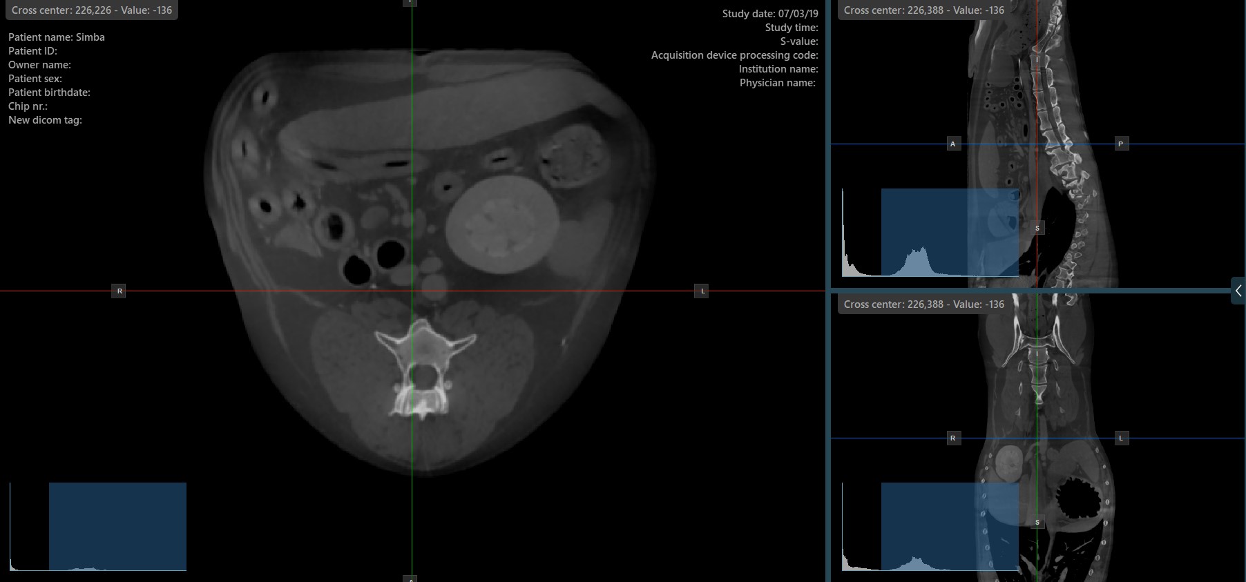
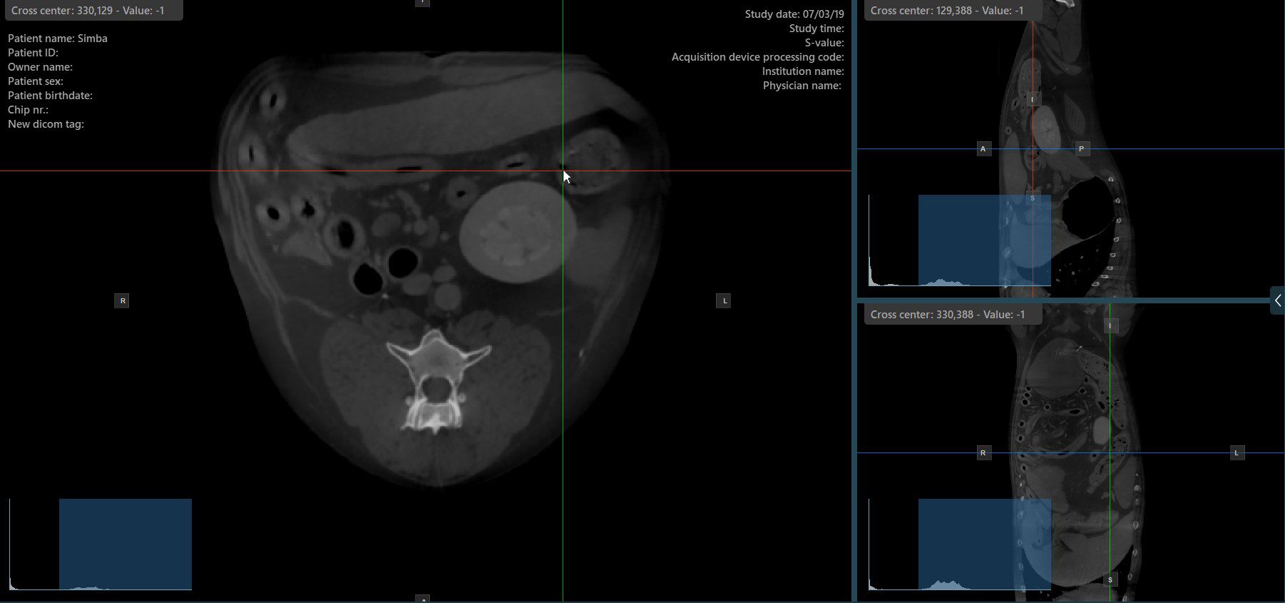
The slicers in MPR view show the intersections and orientation of the three image planes displayed in the active viewports. Users can modify the slicers and change the cross-sectional position of the slices based on the 3D volumetric data.
Each slicers is distinguished by their specific color, which representes the image plane:
The blue slicer marks the axial plane of the object (perpendicular to the ground)
The red slicer marks the coronal plane (parallel to the ground)
The green slicer marks the sagittal plane (perpendicular to the body)
Change Slicer Rotation
Altering the rotation of a slicer will change the orientation of the corresponding image planes. Individual slicers can be selected by using the Select Item (Default) tool, assigned to the right mouse button by default.
Once the specific slicer is selected, drag the slicer in the desired direction to rotate it. The corresponding image plane’s orientation changes accordingly.
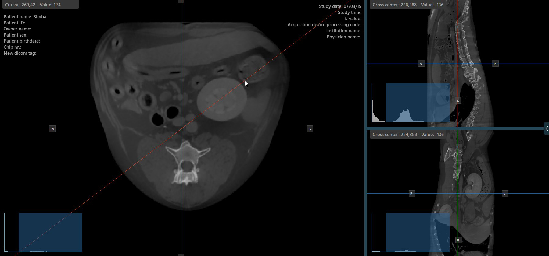

By default, each slicer can be rotated separately. The corresponding icon in the left toolbar of the CT Viewer will be deselected when the slicers are rotated individually.

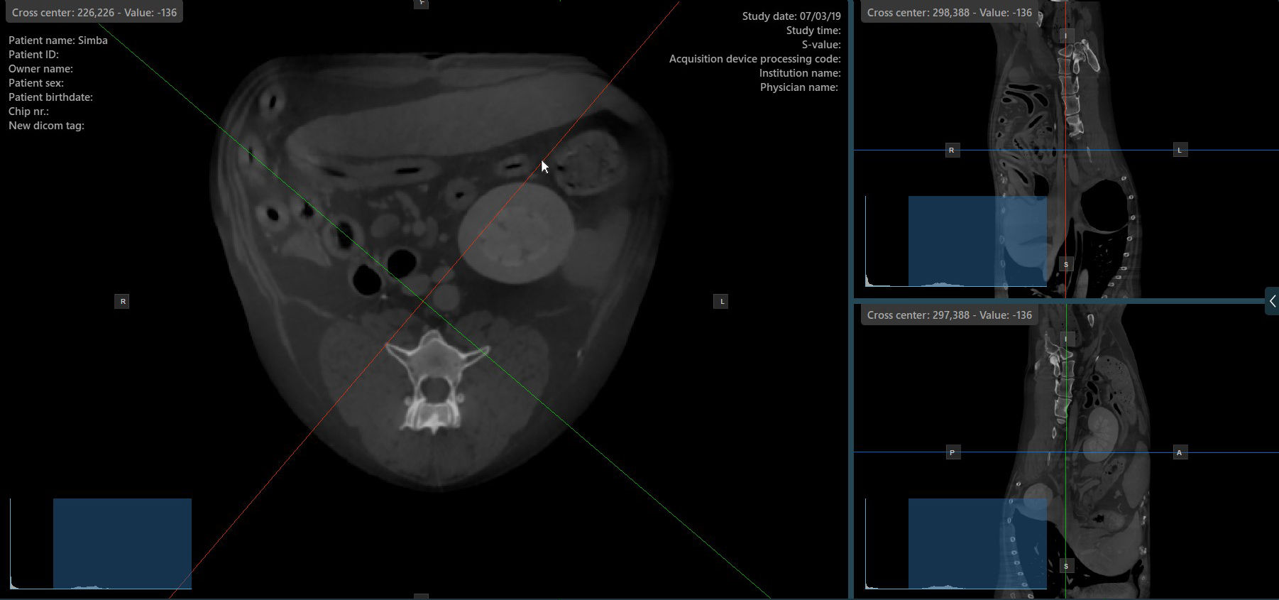
Press the Perpendicular Slicers icon in the left toolbar to activate simultaneous rotation of the slicers. Regardless of their previous orientation, the slicers are repositioned to be perpendicular to each other.
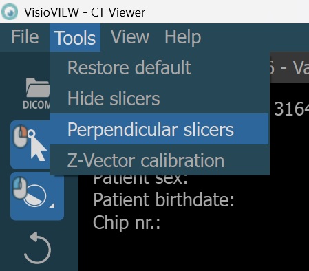
Toggle the Perpendicular Slicers option to switch the active mode of the slicers at any time, or choose one of the Tools -> Perpendicular Slicers or Tools -> Separate Slicers options from the CT Viewer menu.

Change Slicers Cross Center Position
Altering the position of the cross center of slicers will change the position of the corresponding two image planes. The cross center of the slicers can be selected by using the Select Item (Default) tool, assigned to the right mouse
button by default.
Once selected, drag the cross center of the specific slicers to the desired direction to move its position. The corresponding image planes’ orientation changes accordingly.
Show/Hide Slicers

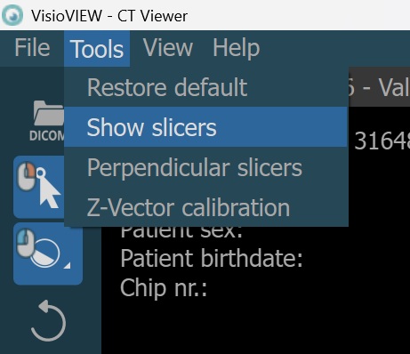
By default, the slicers are visible on the top of the images. The corresponding icon in the left toolbar of the CT Viewer will be selected when the slicers are visible.

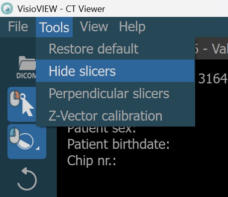
Press the Hide/Show Slicers icon the left toolbar to hide the slicers. The corresponding icon in the left toolbar of the CT Viewer will be deselected when the slicers are hidden.
Users can toggle the visibility of the slicers by using the Hide/Show Slicers option from the left toolbar, or using one of the Tools -> Hide Slicers or Tools -> Show Slicers options from the CT Viewer menu.
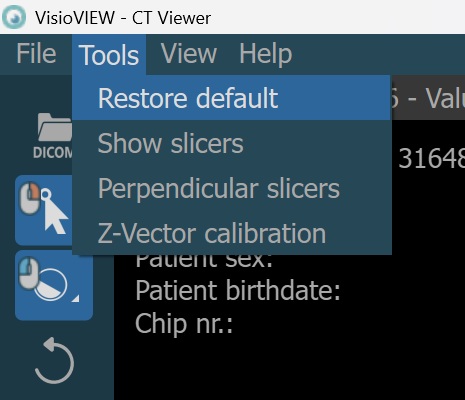
Restore Slicers

To revert the slicers back to their original default state, press the Restore Default icon in the left toolbar. The slicers can also be restored to their default state by using the Tools -> Restore Default option from the
CT Viewer menu.
Information
The Restore Default option also resets the windowing settings, but the measurements on the images stay intact.