Measurement Tools
The VisioVIEW Viewer offers users an extensive set of measurement tools to help in clinical diagnosis of the patients. The measurment tools are located in the left vertical toolbar of the Viewer. They are divided into two sections, simple and advanced measurements.
The following section focuses on the simple measurement in the Viewer. To expand the available simple measurements, press the Simple Measurements button. Collapse the section by pressing on the button again.


Instructions for both simple and advanced measurement tools are displayed in the bottom information bar of the VisioVIEW Viewer. The instructions will guide and assist users when drawing the measurements.

All simple measurement tools can be assigned to different mouse buttons, offering the ability to have multiple tools selected at the same time.
Select/Move Item Tool

Simple measurements are constructed from multiple points. Select existing measurements on the viewer scene to move and adjust them. Measurement values and results are automatically recalculated during modification.
The position of measurement value and result labels of some measurement tools can be modified by moving them to the desired location with the Select/Move Item tool for better readability.


Measurement Point

Measurement Point tool. Each point is assigned with a letter for better identification.Select/Move Item tool. Select the point by using the assigned mouse button of the tool, and then move it freely anywhere on the image.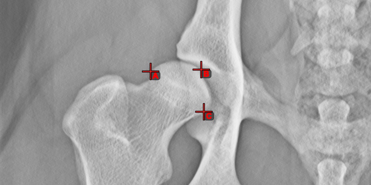
Length Calibration

Distances and measurement results are automatically calibrated based on pixel spacing information in the DICOM image. Use the Length Calibration tool to recalibrate the distances or set the calibration data when the information
is missing in the DICOM file.
Select the
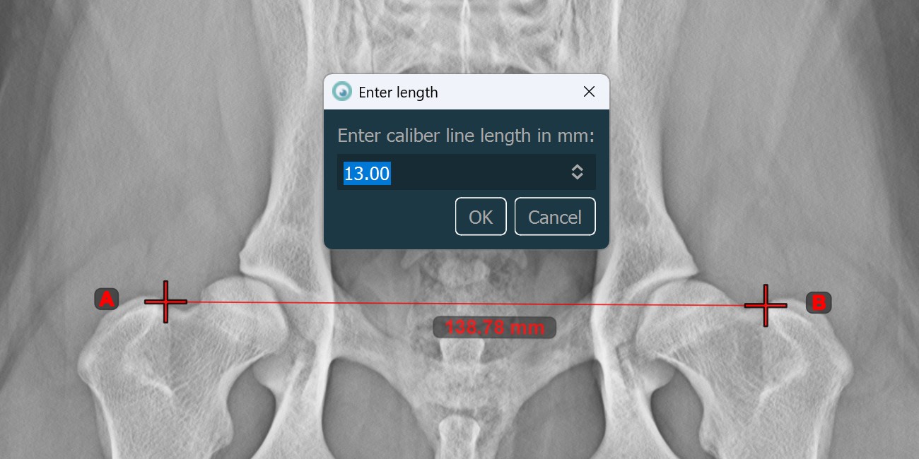
Length Calibrationtool and assign it to one of the available mouse buttons.Measure a known distance on the image by placing the start and end points, or select them from already existing points on the image.
Specify the distance of the calibration line in millimeters and press
OKto recalibrate the image.
Information
Only one Length Calibration measurement is permitted per image. To recalibrate the image again, either unlock the calibration line and modify it, or delete it from the scene and draw it again.
Line Measurement

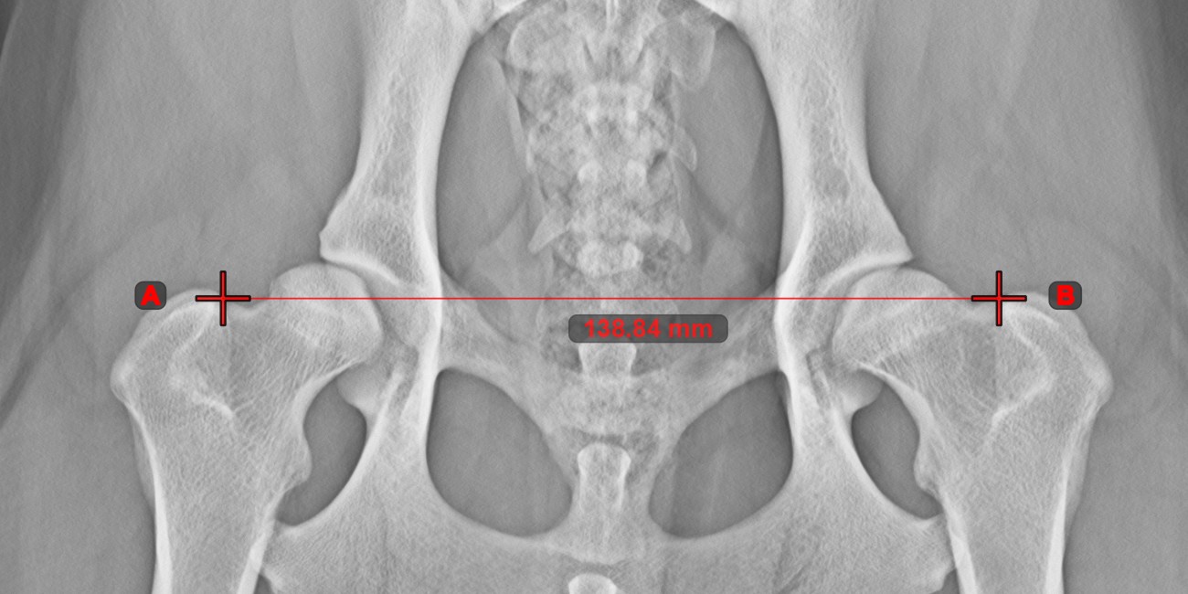
Create a line measurement to calculate the distance between two points with high precision.
Select the Line Measurement tool and assign it to one of the available mouse buttons. Place the start and end points on the scene or select them from already existing points on the image. The distance between the two points will be automatically
calculated by using the default calibration data, or the recalibrated data by the length calibration measurement.
Modify the start and end point by using the Select/Move Item tool. The distance between the two points will be automatically recalculated.
Center Point of Line

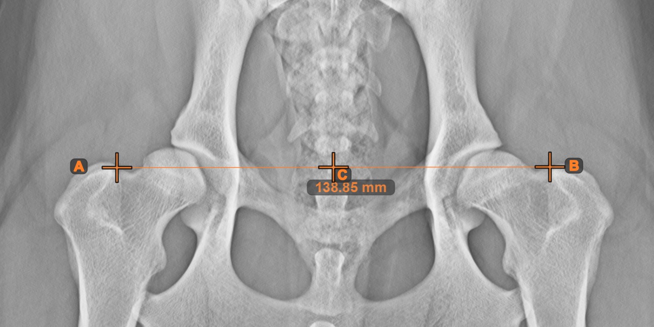
Identify and mark the center point of a new or existing line measurement on the scene by using the Center Point of Line tool.
Select the tool from the left toolbar and assign it to one of the available mouse buttons. Place the start and end points on the scene, select them from already existing points on the image, or select an already drawn line from the scene. The center point of the line will be automatically calculated and placed on the scene. The center point of each line will always be marked with the letter C.
Line Intersection

Quickly and accurately locate and mark the intersection point between two existing lines by using the Line Intersection tool.
Select the tool from the left toolbar and assign it to one of the available mouse buttons. Select two lines that have already been drawn on the scene to complete the measurement. The intersection point of the line will be automatically calculated and marked on the scene. The intersection point of two lines will always be marked with the letter X.
Information
If two lines do not intersect directly, the intersection point of their extended projections on the scene will be marked.


Angle of Lines

Calculate the angle between two independent or intersecting lines by using the Angle of Lines tool.
Select the tool from the left toolbar and assign it to one of the available mouse buttons. Start by selecting the first line from the ones already drawn on the scene, or place the start and end points to create the line. Follow the same steps for the second line of the measurement. The angle between the two lines will be automatically calculated.
Modify the start and end points of both lines by using the Select/Move Item tool. The angle between the two lines will be automatically recalculated.
Information
If two lines do not intersect directly, the angle of their extended projections on the scene will be calculated.


Fixed Angle

Use the Fixed Angle tool to create an angle of lines with a fixed arc. Only the orientation of the angle on the scene can be modified later.
Select the
Fixed Angletool from the left toolbar and assign it to one of the available mouse buttons.Select a line from the ones already drawn on the scene, or mark the start point of the initial side of the angle.
Specify the desired angle in degrees and press
OKto continue.
Mark the end point of the initial side of the angle to complete the measurement. If the user selected a line in the second step, the measurement is automatically completed. The terminal side of the angle is drawn based on the orientation of the initial side and the specified angle in degrees.

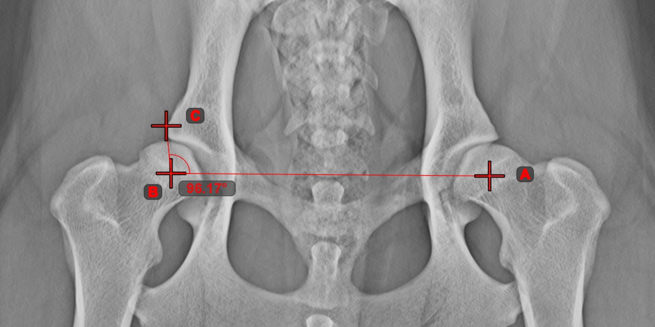
Angle from 3 Points

The Angle from 3 Points tool is a simple and effective way to calculate an angle from just three points.
Start by selecting the tool from the left toolbar and assign it to one of the available mouse buttons. Place the start point of the initial side, the vertex, and the end point of the terminal side of the angle, or select the points from the scene. The sides of the angle will be automatically constructed, thus calculating the angle between the lines.
Modify the position of the three points to change the arc of the angle by using the Select/Move Item tool.
Parallel Line

Create new parallel lines to an existing line on the scene by using the Parallel Line tool.
Select the tool from the left toolbar and assign it to one of the available mouse buttons.
Select the base line for the new parallel line from the existing lines on the scene.
Mark the point on the scene where the parallel line will be drawn through.

Modifying the orientation of the base line automatically changes the orientation of the parallel line. Move the parallel line by selecting and moving the point which the line was drawn through.
Perpendicular Line
Create new perpendicular lines to an existing line on the scene by using the Perpendicular Line tool.
Select the tool from the left toolbar and assign it to one of the available mouse buttons.
Select the base line for the new perpendicular line from the existing lines on the scene.
Mark the point on the scene where the perpendicular line will be drawn through.

Modifying the orientation of the base line automatically changes the orientation of the perpendicular line. Move the perpendicular line by selecting and moving the point which the line was drawn through.
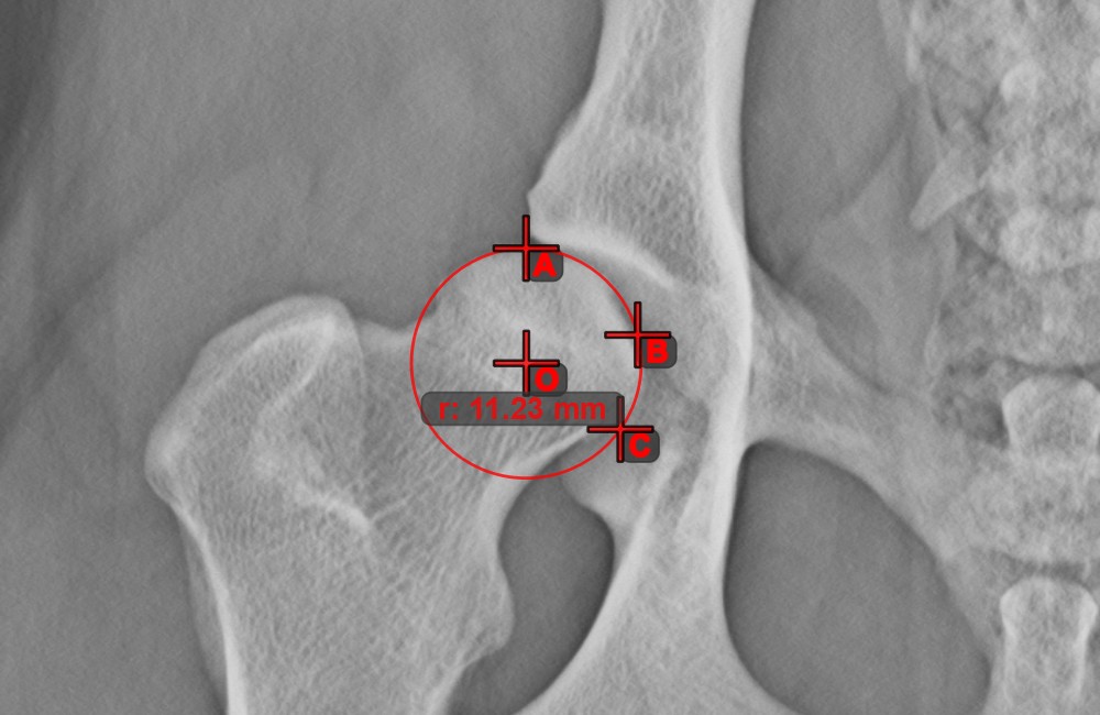
Circle from 3 Points

The Circle from 3 Points tool is a simple and effective way to create a circle from just three points.
Start by selecting the tool from the left toolbar and assign it to one of the available mouse buttons. Place the three points of the circle, or select the points from ones available on the scene. The circle will be automatically created based on the position of the three points. The origo of the circle will always be marked with O. The radius of the circle is automatically calculated.
Modify the position of the three points to change the radius of the circle by using the Select/Move Item tool.
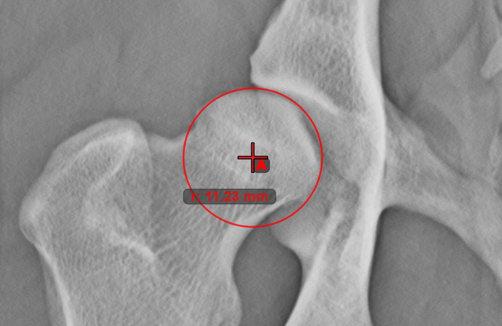
Circle with Defined Radius

Draw a circle with fixed radius by using the Circle with Defined Radius tool. Only the position of the circle on the scene can be modified later.
Select the tool from the left toolbar and assign it to one of the available mouse buttons. Place the origo of the new circle on the scene or select an already existing point. Specify the desired radius of the circle and press OK
to complete the measurement.
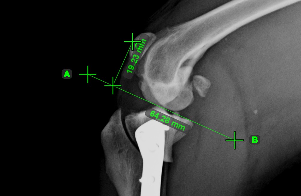
Distance of Line and Point
Measure the distance between a line and a specific point on the scene using the Distance of Line and Point tool.
Select the tool from the left toolbar and assign it to one of the available mouse buttons. Start the measurement by selecting an already existing line from the scene. To complete the measurement, place the desired point on the scene or choose from an already exisiting point. The distance between the line and the point will be automatically calculated.
Modify the measurement by moving any of the points using the Select/Move Item tool.
Text Tool

Label and comment important information on the image by using the Text Tool. The text is always assigned to a point that can be later modified by using the Select/Move Item tool.
Select the tool from the left toolbar and assign it to one of the available mouse buttons.
Mark the point on the scene where the new label will be added.
Specify the text of the label and press
OKto complete the measurement.
